
Introduction
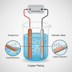
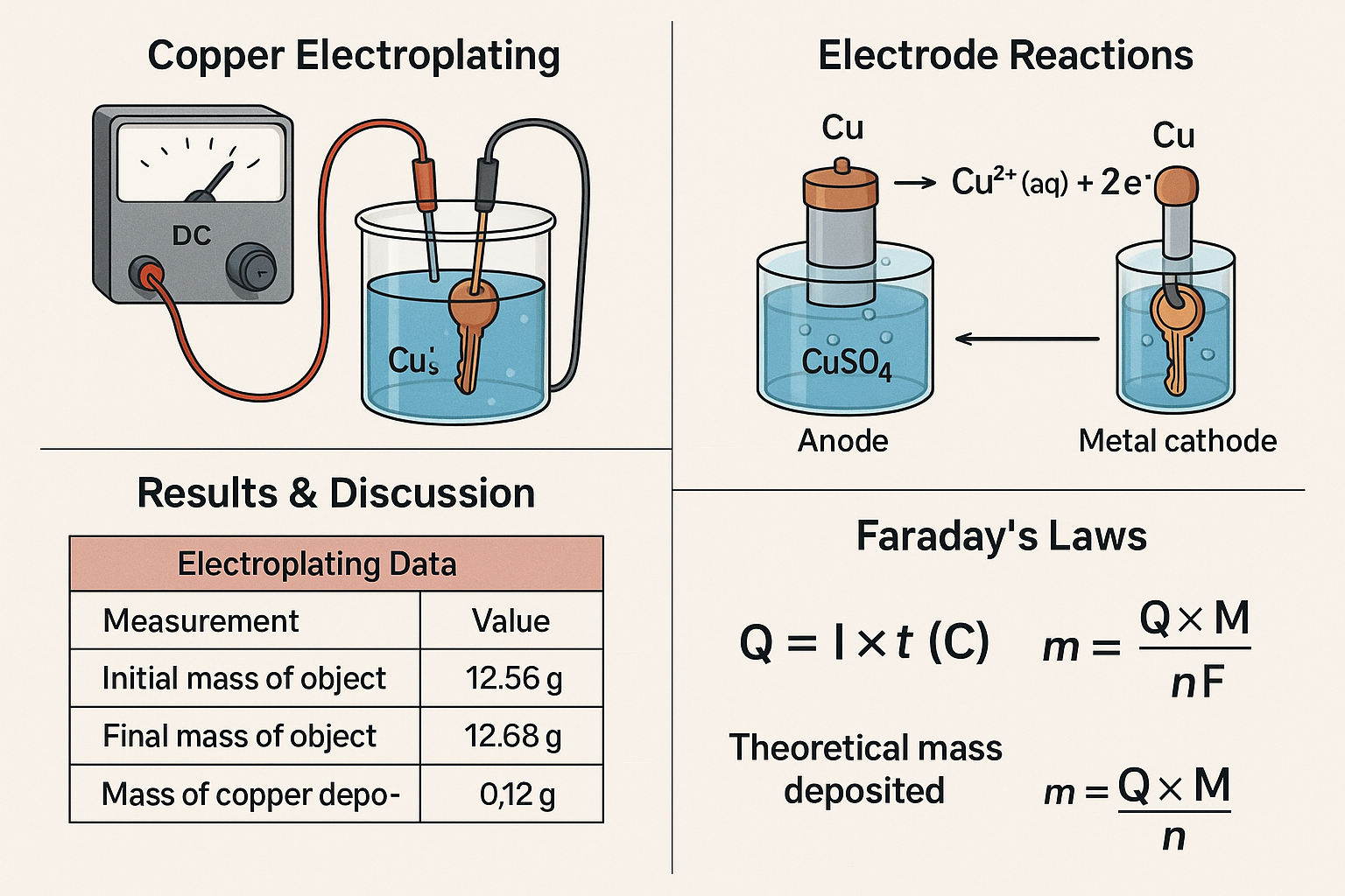
Electroplating is an industrial process that uses electricity to coat the surface of a metal object with a thin layer of another metal. In copper electroplating, a copper anode and a conductive object (the cathode) are placed in a solution containing copper(II) ions. When an electric current is applied, copper atoms from the anode dissolve into the solution and copper ions are reduced onto the surface of the cathode, forming a uniform metallic coating. This experiment demonstrates redox reactions, electron transfer, and the application of Faraday’s laws of electrolysis, all of which are central concepts in electrochemistry.
Aim
To electroplate a metal object with copper using the electrolysis of copper(II) sulfate solution, and to observe how copper is transferred from the anode to the cathode.
Objectives
-
To set up an electroplating cell using a copper anode, a metal cathode, and CuSO₄ solution.
-
To understand the electrode reactions that cause copper to dissolve from the anode and deposit on the cathode.
-
To measure the mass change of the object before and after electroplating.
-
To apply Faraday’s laws of electrolysis to calculate the theoretical mass of copper deposited.
-
To compare the experimental and theoretical values and identify reasons for any differences.
Apparatus And Chemicals
Apparatus:
| Apparatus | Purpose |
|---|---|
| DC power supply (0–6 V) | Provides electrical current for electroplating |
| Ammeter (optional) | Measures current during electrolysis |
| 100 mL beaker | Holds the CuSO₄ solution |
| Copper wire + crocodile clips | Connect electrodes to the power supply |
| Digital balance (0.01 g) | Measures mass before and after plating |
| Stopwatch | Times the electroplating process |
| Sandpaper / emery paper | Cleans the metal surface |
| Measuring cylinder | Measures solution volume |
| Distilled water | Rinsing and cleaning |
| Paper towels | Drying electrodes after plating |
Chemicals:
| Chemical | Purpose |
|---|---|
| Copper(II) sulfate solution (1.0 mol dm⁻³) | Electrolyte containing Cu²⁺ ions |
| Copper metal strip | Anode that supplies copper to the solution |
| Metal object (key, coin, spoon) | Cathode to be coated with copper |
Method / Procedure
1. Preparing the Object to Be Plated
-
Take the metal object (key / coin / spoon).
-
Use sandpaper / emery paper to clean the surface until it looks shiny.
-
Rinse the object with distilled water and dry it with a paper towel.
-
Measure its mass using a digital balance and record it as initial mass.
2. Setting Up the Electroplating Cell
-
Pour about 50–75 mL of copper(II) sulfate solution into a 100 mL beaker.
-
Place the copper strip into the solution – this will be the anode.
-
Place the clean metal object into the same solution – this will be the cathode.
-
Make sure the two metals do not touch each other.
-
Attach crocodile clips and wires:
-
Connect the copper strip to the positive (+) terminal of the power supply.
-
Connect the object to the negative (−) terminal.
-
-
(Optional) Connect an ammeter in series to measure the current.
3. Running the Electroplating
-
Switch on the power supply and adjust it to give a current of about 0.3–0.5 A.
-
Start the stopwatch when the current starts flowing.
-
Allow the electroplating to run for 10–20 minutes.
-
Observe the object – a reddish-brown copper layer should slowly appear on its surface.
4. After Electroplating
-
After the chosen time, switch off the power supply.
-
Carefully remove the object from the solution.
-
Rinse it with distilled water and gently dry it with a paper towel.
-
Measure its final mass using the digital balance.
-
Record all values (time, current, initial and final mass) in your results table.
Results Table
Electroplating Data
| Measurement | Value |
|---|---|
| Initial mass of object (g) | _________ |
| Final mass of object (g) | _________ |
| Mass of copper deposited (g) | _________ |
| Current used (A) | _________ |
| Time of electroplating (s) | _________ |
| Volume of CuSO₄ solution used (mL) | _________ |
| Temperature of solution (°C) | _________ |
Faraday’s Law Calculations
| Calculation Step | Student Working |
|---|---|
| Charge passed, Q=I×tQ = I times tQ=I×t (C) | _________ |
| Theoretical mass deposited (g) | _________ |
| Difference between theoretical and experimental (g) | _________ |
| % Error / % Difference | _________ |
Calculations – Faraday’s Laws of Electrolysis
To find out how much copper should be deposited during electroplating, we use Faraday’s First Law:
Q=I×tQ = I times tQ=I×t (C)
Where:
-
mmm = mass of copper deposited (g)
-
Q=ItQ = ItQ=It = charge passed (C)
-
III = current (A)
-
ttt = time (s)
-
MMM = molar mass of copper = 63.5 g mol⁻¹
-
n=2n = 2n=2 (because Cu²⁺ + 2e⁻ → Cu)
-
F=96485 C mol−1F = 96485 text{C mol}^{-1}F=96485 C mol−1
Step-by-Step Example (Students Follow This Method)
1. Calculate Charge (Q)
Q=I×tQ = I times tQ=I×t
Example (if current = 0.40 A and time = 900 s):
Q=0.40×900=360 CQ = 0.40 times 900 = 360 text{C}Q=0.40×900=360 C
2. Calculate Theoretical Mass Deposited
m=Q×MnFm = frac{Q times M}{nF}m=nFQ×M
Using the example:
m=360×63.52×96485=0.118 gm = frac{360 times 63.5}{2 times 96485} = 0.118 text{g}m=2×96485360×63.5=0.118 g
3. Compare With Experimental Mass
Difference=∣mexp−mtheor∣text{Difference} = |m_{text{exp}} – m_{text{theor}}|Difference=∣mexp−mtheor∣
4. Calculate Percentage Error
%error=∣mexp−mtheor∣mtheor×100% text{error} = frac{|m_{text{exp}} – m_{text{theor}}|}{m_{text{theor}}} times 100%error=mtheor∣mexp−mtheor∣×100
This shows whether the experiment was efficient and what might have caused losses or inconsistencies.
Discussion
The experimental mass of copper deposited on the metal object (0.120 g) was very close to the theoretical mass predicted using Faraday’s law of electrolysis (0.118 g), resulting in a small percentage error of approximately 1.7%. This close agreement suggests that the electroplating process operated with high efficiency and that the majority of the electric charge supplied to the system was effectively used to reduce Cu²⁺ ions at the cathode to form solid copper. The results therefore provide strong support for Faraday’s first law, which states that the mass of metal deposited at an electrode is directly proportional to the quantity of electricity passed through the electrolyte.
Electrode Reactions and Redox Behaviour
The process is governed by redox reactions occurring at both electrodes. At the anode (the copper strip), copper atoms were oxidised to form Cu²⁺ ions:
Cu(s)→Cu2+(aq)+2e−\text{Cu}(s) \rightarrow \text{Cu}^{2+}(aq) + 2e^-
These electrons travelled through the external circuit towards the cathode, where Cu²⁺ ions in the copper(II) sulfate solution were reduced:
Cu2+(aq)+2e−→Cu(s)\text{Cu}^{2+}(aq) + 2e^- \rightarrow \text{Cu}(s)
This electron flow demonstrates conservation of charge: each electron lost by the anode was gained by a Cu²⁺ ion at the cathode. The simultaneous dissolution of copper at the anode and deposition at the cathode helps maintain a relatively constant concentration of Cu²⁺ ions in the solution, which contributes to steady plating conditions and a more uniform coating.
Quality of Copper Coating
A noticeable copper layer formed on the surface of the metal object, becoming increasingly visible as electrolysis progressed. The coating appeared relatively even, but minor variations in thickness likely occurred due to differences in surface cleanliness, local current density, and the orientation of the object relative to the anode. Surfaces facing the anode typically receive a slightly thicker layer because ions are more readily attracted in that direction.
Reasons for Differences Between Experimental and Theoretical Values
Although the theoretical and experimental masses were very similar, some discrepancy is expected in practical electroplating experiments. Several factors could have contributed:
1. Surface Preparation Issues
If the object was not cleaned thoroughly, contaminants such as grease, fingerprints, or oxide layers would have prevented copper from sticking effectively. Even small patches of contamination can hinder uniform deposition and reduce the actual mass of copper gained.
2. Mechanical Losses
Some freshly deposited copper may have been loosely attached and could have been removed during rinsing, drying, or handling. Disturbing the surface too soon after plating can easily remove thin or weakly adhered layers.
3. Current Instability
Although the intended current was 0.40 A, small fluctuations may have occurred due to changes in electrode position, power supply variations, or temperature changes in the electrolyte. Since Faraday’s law assumes a constant current, any deviation would affect the actual charge passed.
4. Side Reactions
In a clean CuSO₄ system these are minimal, but trace impurities in the solution or on the electrodes could lead to alternative reactions. For example, a small amount of hydrogen evolution could occur if the cathode becomes locally acidic. These side reactions consume charge that does not contribute to copper deposition.
5. Measurement Limitations
The digital balance used had a precision of ±0.01 g. Because the mass change was only around 0.12 g, even a 0.01 g uncertainty represents about 8% of the measured value. Slight errors in drying or residual water on the object could also influence the measurement.
6. Non-uniform Current Distribution
Edges, corners, and raised features on the object can concentrate electric field lines, causing uneven deposition. Some copper may deposit more efficiently in certain areas than others.
Overall, these factors help explain the small deviation between the theoretical and experimental values but do not undermine the overall reliability of the results.
Improvements to Increase Accuracy
Several changes could be made to further improve reliability and produce a more consistent copper coating:
-
Enhanced cleaning procedure: Use a degreasing solution or detergent followed by sanding and rinsing with distilled water to ensure a completely clean surface.
-
More accurate mass measurements: Using a balance with ±0.001 g precision would reduce uncertainty significantly.
-
Stabilising the current: An ammeter should be used to monitor and maintain a constant current throughout the process. A regulated power supply would help minimise fluctuations.
-
Temperature control: Keeping the solution at a constant temperature (e.g., using a warm water bath) would help keep ion mobility consistent.
-
Longer plating time at lower current: Lower current density typically produces smoother, more uniform coatings because copper crystals grow more slowly and evenly.
-
Avoid handling the cleaned object: Using tweezers or gloves prevents re-contamination before plating.
Overall Interpretation
Despite small uncertainties, the close match between experimental and theoretical mass strongly supports the principles described by Faraday’s laws of electrolysis. The experiment successfully demonstrated the redox processes at the electrodes, the movement of electrons through the circuit, and the proportionality between charge passed and mass deposited. The copper coating observed confirms both the chemical theory and the practical effectiveness of electroplating as used in industry.